Technical
Programmable Breadboard
September 2024 - November 2024
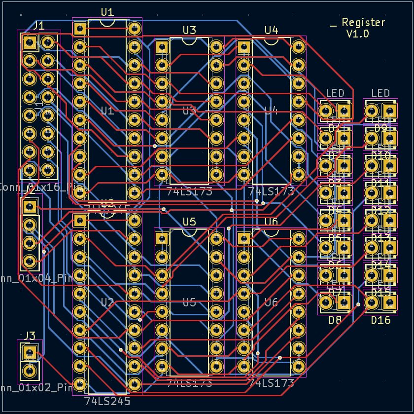
A programmable breadboard that simulates pin connections in software and exports a KiCad netlist, turning breadboard circuits into PCB layouts without redrawing the schematic.
The Problem
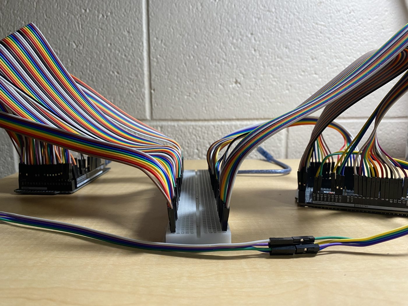
I needed this while designing the many PCBs for the 16-bit computer, both to speed up layout and to remove errors when converting breadboard circuits to a schematic. The original inspiration was a hackathon project that used analog crosspoint switches so signals could pass from one pin to another. That does not scale: the number of crosspoint switches grows quadratically with every pin. For 16×8 analog crosspoint switches, 64 chips would be needed for a full-sized breadboard (128 pins total). Because I planned the board for digital circuits, pin connections are simulated with Arduinos instead.
How It Works
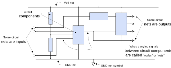
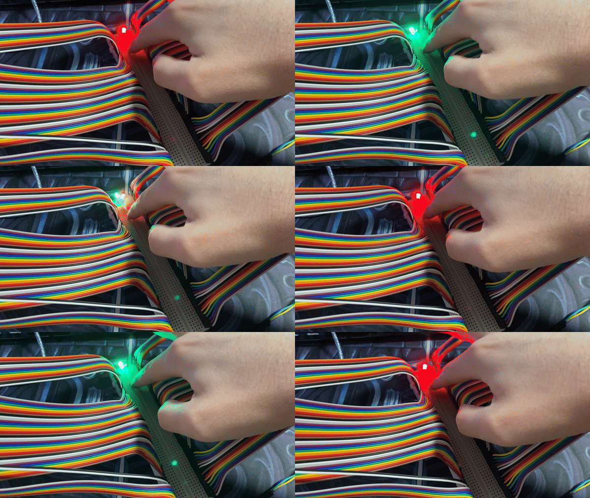
Any pins in use are assigned to different nets, just like in a PCB schematic, which makes it easy to track pins in software and assign voltages appropriately. The breadboard uses two Arduino Megas communicating through I2C. When a read pin on one Arduino detects a state change (0–1 or 1–0), it writes that new state to its net array and sends a message to the other Arduino. The other Arduino assigns the new state to its own net array. Once both arrays are updated, the Arduinos write the new state to the breadboard pins.
The Software
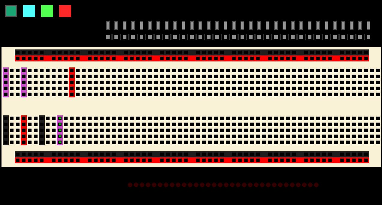
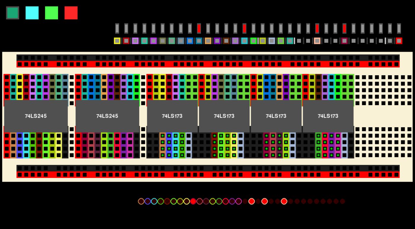
The Arduinos communicate with the computer over UART. The breadboard can be assigned manually through a serial port, or through a Python application I wrote for easier configuration. The app can be set up with logic chips as a visual representation of what is on the breadboard. Clicking two pins creates a net between them; clicking more pins while a net is selected adds them to it. A row of completely virtual pins and LEDs lets inputs and outputs be added without placing physical components. Designs can be saved to a JSON file and loaded later.
Export
Once a design is working, the nets and components can be exported to a netlist and imported directly into KiCad. That cuts out drawing a circuit schematic; component placement and trace routing can start immediately. Because of this pipeline, the circuits work physically and import into a PCB design reliably. Eventually all of the Arduino-to-breadboard connections would sit on a PCB that presses onto the breadboard, to keep everything neater and keep wires from unplugging.